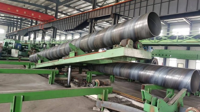
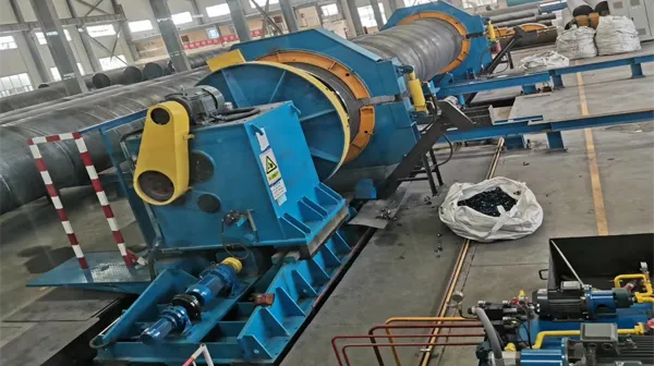
How Should a Spiral Pipe Mill Be Configured for Different Pipe Diameters and Wall Thicknesses?
Configuring a spiral pipe mill for different pipe diameters and wall thicknesses requires more than adjusting a few machine settings. Steel strip width, forming angle, roller positions, welding parameters, and line speed must work together to meet the target pipe dimensions and weld quality requirements.
Each change in specification must be evaluated against the mill's design limits, followed by a controlled setup and inspection process.
This guide explains which parameters may need adjustment when pipe dimensions change, how to coordinate the production line during changeovers, and what to verify before returning to full production.
Step 1: Define Pipe Specifications and Confirm Equipment Capacity
Before configuring the mill, establish a specification matrix covering pipe diameters, wall thicknesses, steel grades, strip widths, and required pipe lengths. Compare these requirements with the mill’s rated forming capacity, roller adjustment range, welding system, and cutting capacity. For oil and gas pipeline projects, the applicable product requirements can be referenced in ISO 3183:2019 for steel pipes used in pipeline transportation systems.
For each product, record the approved setup parameters and inspection results. Do not assume that a mill can produce every combination of its maximum pipe diameter and maximum wall thickness. Confirm that each required combination falls within the equipment's designed operating range.
Step 2: Adjust the Forming System to Match the Target Pipe Diameter
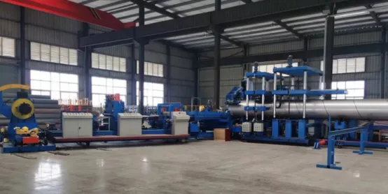
Coordinate strip width, forming angle, and roller settings
When changing to a different pipe diameter, use the machine’s approved setup data to guide the adjustment process:
Confirm the steel strip width. Select the width specified for the target pipe diameter and forming configuration.
Set the forming angle and feed position. Establish the required forming geometry using the approved machine settings.
Adjust the rollers and guides. Position each component according to the target diameter and the equipment manufacturer’s instructions.
Run a controlled trial. Measure the resulting pipe diameter and roundness, then check edge alignment and spiral seam position before resuming normal production.
These adjustments should not be treated as independent settings. The relationship between strip width, forming angle, and pipe diameter depends on the machine design and forming method. Rather than applying a universal adjustment formula, use the configuration data established for the specific mill and verify the resulting geometry through trial production.
Step 3: Match Forming and Welding Conditions to Wall Thickness
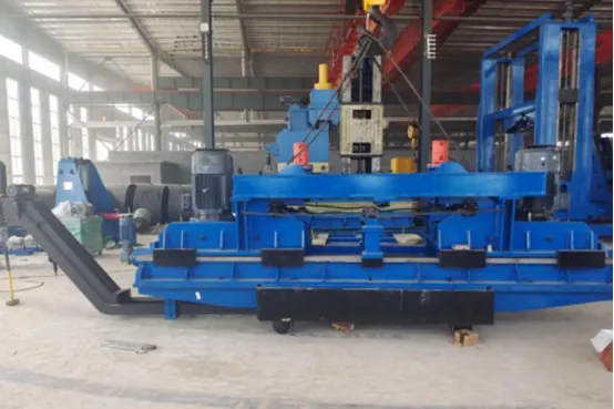
A change in wall thickness can affect both the mechanical demands of forming and the conditions required for a sound weld. The forming system must accommodate the material thickness and associated forming load, while the welding system must maintain the required seam quality at the selected production speed. Before making adjustments, confirm that the mill’s rollers, drive system, and machine structure can handle the target material thickness and forming requirements.
Welding current, voltage, travel speed, and welding head configuration should be evaluated together based on the steel grade, wall thickness, welding process, and joint conditions. The applicable wire arrangement and internal and external welding setup must also match the target specification. Do not automatically reuse the same welding parameters for every wall thickness, as changes in heat input, travel speed, and edge alignment can affect weld quality. Establish the final settings through the applicable qualified welding procedure, then inspect a trial weld for seam appearance, penetration, and other required quality indicators before approving full production.
Step 4: Coordinate the Entire Production Line During Changeovers
A pipe specification change affects more than the forming machine. Strip preparation, feeding, welding, cutting, and pipe handling must all support the new product dimensions and production conditions.
Equipment group | Adjustment or verification required |
Uncoiling and leveling | Confirm coil dimensions and strip preparation requirements |
Strip feeding and guiding | Reset the feed position and verify strip alignment |
Forming system | Set the forming angle and roller positions for the target diameter |
Internal and external welding | Apply approved welding parameters for the material and wall thickness |
Cutting system | Set the required pipe length and verify cutting accuracy |
Pipe support and output | Confirm that support and handling arrangements suit the new pipe diameter |
Control and hydraulic systems | Load or record the applicable settings and verify operating conditions |
Step 5: Verify Pipe Dimensions and Weld Quality Before Full Production
After each specification change, produce a trial section and verify that it meets the required dimensional and weld quality criteria. Check pipe diameter, roundness, spiral seam position, weld quality, and cutting accuracy against the applicable product specifications.
If a measurement falls outside the required tolerance, identify the relevant forming, feeding, welding, or cutting parameter and correct it before continuing production. For line pipe applications, API Specification 5L defines requirements covering pipe manufacturing, inspection, testing, and traceability. Apply the standard when relevant to the product and project requirements.
Showcase of TXH's Project Cases
The 3620 Spiral Pipe Mill project in Bangladesh demonstrates TXH’s experience in large-diameter pipe production. The published specifications cover pipe diameters of 630–3,620 mm and wall thicknesses of 6.0–25.4 mm for large-scale water transmission projects. During the design stage, TXH work with customers to confirm target pipe specifications, evaluate equipment capacity, and plan the forming, welding, and cutting system configurations.
Conclusion
Configuring a spiral pipe mill for different pipe diameters and wall thicknesses requires a coordinated approach to equipment capacity, forming geometry, welding conditions, and quality inspection. The correct settings depend on the target pipe specification and the design limits of the individual production line.
Before approving a configuration, confirm that the required diameter-and-thickness combinations fall within the mill’s operating range, establish the relevant forming and welding parameters, and verify the first trial section against the specified quality requirements.
Frequently Asked Questions
Can one spiral pipe mill produce different pipe diameters and wall thicknesses?
Yes, provided the required diameter-and-thickness combinations fall within the mill’s designed operating range. Forming settings and welding parameters must be evaluated and verified for each specification.
Which parameters need adjustment when changing pipe diameter?
Depending on the machine design, the main parameters may include steel strip width, forming angle, feed position, roller settings, and spiral seam position. Use the mill’s approved setup data to determine the required adjustments.
What changes when wall thickness increases?
The forming load and welding requirements may change. Confirm the mill’s forming capacity and establish suitable welding current, voltage, travel speed, and welding head configuration for the actual material and process.
References / External Resources
ISO 3183:2019 — Petroleum and Natural Gas Industries: Steel Pipe for Pipeline Transportation Systems Anchor text: ISO 3183:2019 steel pipe manufacturing requirements
URL: https://www.iso.org/standard/76676.html
API Specification 5L — Line Pipe Anchor text: API Specification 5L line pipe manufacturing and inspection requirements