English
×
Search
Ultrasonic testing and X-ray inspection can both reveal internal weld discontinuities without cutting a steel pipe apart, but they provide different evidence. Ultrasonic testing is easier to integrate into many continuous lines and can locate and size crack-like flaws. X-ray inspection creates an image that is useful for reviewing porosity, inclusions and incomplete penetration. The right method depends on defect orientation, weld geometry, production speed, safety controls and the governing standard.
Non-destructive testing is the examination of a material, component or weld for discontinuities without impairing its future usefulness.
Ultrasonic testing sends high-frequency sound waves into the pipe wall and analyzes returning echoes. A probe introduces sound at a selected angle so that the beam crosses the weld and heat-affected zone. Reflections from boundaries or discontinuities appear as signals that trained personnel interpret.
The American Society for Nondestructive Testing describes UT as a method that detects and measures discontinuities by analyzing returned sound-wave echoes. ISO 17640:2018 covers manual ultrasonic testing of fusion-welded metallic joints at least 8 mm thick, primarily full-penetration ferritic welds, and defines four testing levels. Automated applications require requirements established by the relevant specification.
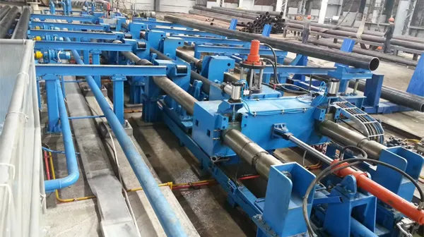
For continuous production, automated ultrasonic pipe testing can combine multiple channels, real-time processing and digital recording. TXH’s system inspects pipe welds and pipe bodies with water-film coupling and can generate inspection reports.
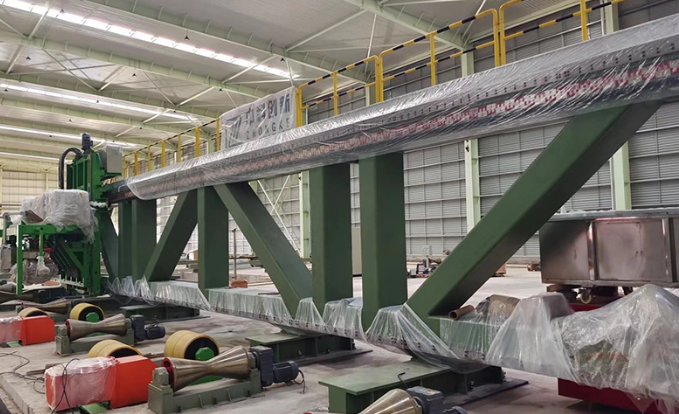
Radiographic testing passes ionizing radiation through the weld and records differences in transmitted intensity. Changes in thickness or density create contrast on the resulting image. Radiographic testing uses X-rays or gamma rays to produce a visible representation of a component’s internal structure.
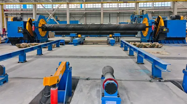
A digital pipe x ray machine normally combines a radiation source, detector, image-processing system, mechanical handling, controls and a shielded enclosure. TXH’s real-time system is designed for spiral steel pipe weld inspection and digital image review.
Radiography offers a recognizable record of indication position and shape. Its limitation is the need to control ionizing radiation through shielding, restricted access, monitoring and trained personnel under applicable regulations. Radiographic testing presents inherent safety risks when proper precautions are not followed.
| Selection factor | Ultrasonic testing | X-ray inspection |
| Physical principle | Reflected high-frequency sound | Radiation attenuation |
| Typical strength | Planar flaws and sizing information | Volumetric flaws and image records |
| Result format | Signal display or encoded map | Digital radiographic image |
| Line integration | Well suited to automated scanning | Possible with shielding and handling |
| Access requirement | Often one accessible surface | Source and detector positioned across the weld |
| Main safety issue | Couplant and moving equipment | Ionizing radiation |
| Best fit | Continuous inspection and flaw sizing | Image-based review of density changes |
Neither method is universally superior. A planar flaw may reflect an ultrasonic beam strongly but produce little radiographic contrast. A rounded pore may be clear on an X-ray image but less distinctive in an ultrasonic signal. Inspection sensitivity therefore depends on defect shape, orientation, material properties and test geometry.
Defect orientation matters as much as defect size. UT depends on sound returning toward the probe, while radiographic visibility depends on density or thickness change along the radiation path.
Common inspection targets include:
Cracks and lack of fusion: often suited to correctly angled ultrasonic beams.
Porosity and slag inclusions: often displayed clearly by radiography.
Incomplete penetration: detectable by either method with suitable geometry.
Lamination and wall-thickness variation: commonly assessed ultrasonically.
Misalignment and surface profile: better checked by visual or dimensional inspection.
Finding an indication does not automatically mean rejection. The applicable pipe specification, welding code or customer requirement determines calibration, inspection coverage and acceptance criteria. ISO 17640, for example, allows discontinuities to be assessed through echo amplitude and length or through characterization and sizing using probe movement.
Automated UT is often selected for high-throughput screening because probes can scan moving pipe and process signals immediately. Actual speed depends on pipe diameter, weld path, channel count and required coverage. TXH’s automatic ultrasonic system uses real-time signal acquisition and processing, defect evaluation and digital data storage.
Real-time X-ray inspection can also be automated, but the line must accommodate shielding, interlocks and controlled access. A complete TXH X-ray system includes a protective lead room, monitoring system, detector, mechanical transmission and automatic control equipment.
Before comparing equipment, manufacturers should define:
Weld-only, heat-affected-zone or full-body coverage.
Pipe diameter, wall thickness, material and weld configuration.
Required sensitivity, acceptance criteria and reference standards.
Data-storage, traceability and report format.
Available space, handling method and radiation-safety boundary.
The fastest detector will not improve production output if loading, calibration or result review becomes the bottleneck. Equipment performance must therefore be evaluated as part of the complete inspection station rather than as an isolated detector.
UT and X-ray are often complementary. Automated UT can provide continuous screening, while radiography can examine selected weld areas, qualification samples or indications requiring image-based confirmation. The inspection plan should follow the governing specification rather than assume one method replaces every other quality check.
Neither method proves pressure performance. A hydro testing machine for pipe applies internal fluid pressure to reveal leakage, deformation or failure under specified test conditions. TXH’s hydrostatic systems seal the pipe ends, fill the pipe with fluid, raise the pressure and record the test result.
For equipment procurement, confirm:
Applicable API, ISO, ASTM or customer specification.
Target defects and acceptance criteria.
Pipe range, wall thickness and production rate.
Manual, semi-automatic or automatic handling.
Probe, calibration block or detector configuration.
Shielding, interlocks, training and licensing needs.
Data storage and production-line control integration.
TXH can configure ultrasonic and real-time X-ray equipment around pipe dimensions, inspection coverage and line layout, but these requirements should be agreed before equipment design.
Choose ultrasonic testing for continuous scanning, flaw sizing and production-line integration. Choose X-ray inspection when a visual record of density-related weld defects is especially valuable. Critical pipe production may require both methods together with visual inspection and hydrostatic testing under the applicable product standard.
Automated UT is generally easier to run continuously without a radiation-controlled area. Actual throughput depends on inspection coverage, pipe handling, calibration and reporting requirements.
UT is often preferred for planar cracks and lack of fusion when the beam angle is suitable. Crack orientation, surface condition and weld geometry still affect detection.
Radiography is commonly effective for porosity and inclusions because these discontinuities can create visible density differences on the resulting image.
Only when the governing specification permits the substitution and a qualified UT procedure provides the required coverage, sensitivity and acceptance assessment.
No. UT and radiography examine material and weld discontinuities, while hydrostatic testing evaluates how the completed pipe responds to internal fluid pressure.
Provide the pipe diameter, wall thickness, material, weld type, production speed, target defects, applicable standard, acceptance criteria, automation level and reporting requirements.