What NDT Equipment Is Typically Required in a Spiral Welded Pipe Production Line?
A spiral welded pipe line needs coordinated inspection equipment. Automated ultrasonic testing (UT) commonly examines weld seams, while radiographic testing (RT) and surface methods may be added to meet product or project requirements. The setup depends on pipe dimensions, weld geometry, target defects, and required coverage.
What NDT Equipment Is Commonly Used on a Spiral Welded Pipe Line?
Equipment | Main Purpose |
Automated UT system | Inspect weld seams and specified adjacent areas |
RT system | Produce film or digital images of internal weld conditions |
MT / PT tools | Examine surface and near-surface discontinuities |
ET / MFL systems | Detect selected indications in suitable materials |
Calibration pieces | Verify inspection sensitivity and response |
Not every line needs every method. UT is commonly used for weld-seam inspection. RT, magnetic particle testing (MT), liquid penetrant testing (PT), eddy-current testing (ET), or magnetic-flux-leakage testing (MFL) are selected when required by the material, standard, or inspection task.
What Is Included in an Automated Ultrasonic Testing System?
An automated ultrasonic pipe testing equipment system may include:
Flaw detector and probes: Multi-channel instruments inspect weld seams, heat-affected zones, pipe bodies, or pipe ends.
Probe tracking: Adjustable holders keep probes aligned with the spiral seam as the pipe moves or rotates.
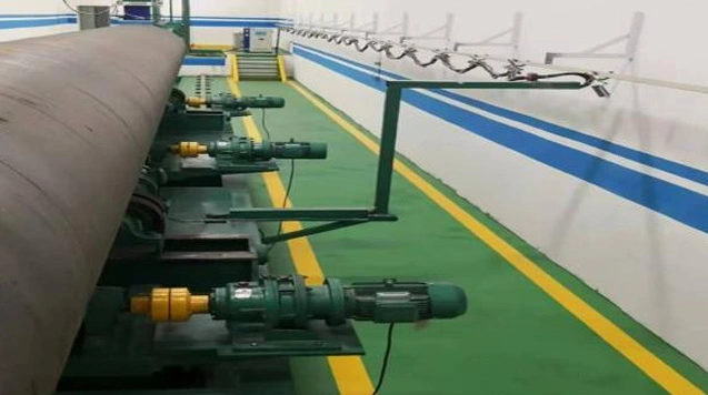
Pipe handling: Rollers, rotation drives, and conveyors maintain a stable scanning path.
Couplant system: A controlled water film transfers ultrasonic energy into the pipe.
Control and marking: Computers collect signals, locate indications, generate reports, and trigger alarms or markers for suspect areas.
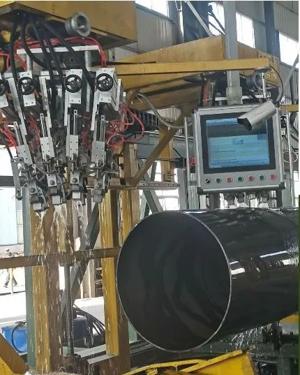
Depending on the inspection plan, systems may use straight- or angle-beam probes, multiple scan directions, PAUT, or TOFD for specified weld regions and defect orientations.
When Is Radiographic Testing or Surface Inspection Equipment Needed?
An industrial X-ray equipment for steel pipe inspection system may include an X-ray source, film or digital detector, image-processing workstation, mechanical positioning, and a protective lead room. Film, computed radiography (CR), and digital radiography (DR) are possible recording methods.
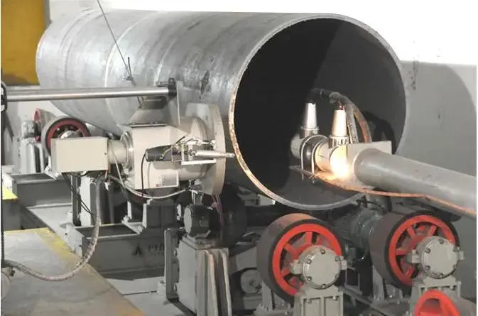
RT provides an image record and is useful for volumetric indications such as porosity and slag inclusions. Tight planar flaws may be less visible when their orientation is unfavourable to the radiation beam.
MT and PT examine surface or near-surface flaws. MT applies to ferromagnetic steel, while PT reveals surface-breaking flaws on clean, non-porous surfaces. ET and MFL may be selected for specific conductive or ferromagnetic materials. These methods do not replace weld-seam UT or RT.
What Supporting Equipment Is Needed for Reliable Inspection?
UT systems should be checked with reference blocks or pipes containing known reflectors. Probe selection, sensitivity, scanning speed, and evaluation thresholds must follow the inspection procedure. Calibration should be verified at required intervals and whenever setup conditions change.
Manual scanners may support local follow-up inspection. A demagnetization unit may be needed if welding-induced magnetism affects radiographic images or later field welding; this is conditional.
Hydrostatic testing equipment may be installed downstream, but pressure testing is not NDT. It checks pressure integrity rather than locating or sizing internal weld indications.
How Is NDT Equipment Integrated into a Spiral Pipe Mill?
Planning starts with pipe grade, diameter, wall thickness, weld geometry, applicable standards, and required coverage. The line must allow the pipe to move or rotate while probes and detectors maintain their positions.
During inspection, the system tracks the seam, acquires signals or images, and records indication locations. Suspect areas are marked and evaluated against acceptance criteria; repaired areas are re-examined. Where full-length coverage is required, the procedure must define how it is achieved and verified.
Records should link inspection results to pipe identification, calibration status, procedure, equipment setup, coverage, indication location, and repair or retest history. When configuring a spiral welded pipe production line, buyers should define inspection stages alongside forming, welding, and downstream testing. A spiral pipe mill coordinates inspection with pipe movement and production records.
FAQs About NDT Equipment for Spiral Welded Pipe
1. Is an automated UT system essential for every spiral welded pipe line?
Not universally. The required method and coverage depend on product standards, project specifications, pipe dimensions, and the inspection plan.
2. Does a spiral pipe line also need an X-ray inspection system?
RT may be required for supplementary or project-specific inspection. Its use depends on target defects, access, and radiation-safety arrangements.
3. What is the purpose of calibration blocks in UT inspection?
Reference blocks or pipes with known reflectors check probe response and system sensitivity against the approved procedure.
4. Can a hydrostatic tester replace NDT equipment?
No. Hydrostatic testing checks pressure integrity, while NDT methods locate or evaluate discontinuities. They serve different purposes.