X-Ray vs Ultrasonic Testing for Spiral Welded Pipe: When Is Each Method Used?
X-ray testing (RT) and ultrasonic testing (UT) examine spiral pipe welds without cutting the pipe. RT uses radiation imaging; UT analyses reflected sound waves. Selection depends on defect type, pipe dimensions, weld geometry, coverage, and project requirements.
What Does X-Ray Testing Show in a Spiral Welded Pipe?
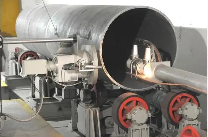
RT directs X-rays or gamma rays through the weld to a film or digital detector. Differences in thickness and density affect radiation absorption, creating image contrast for inspectors.
RT is useful for volumetric indications such as porosity and slag inclusions. It may also reveal incomplete penetration when defect orientation and exposure provide sufficient contrast. Tight planar defects may be difficult to identify when their orientation is unfavourable to the beam. RT requires access for source and detector, plus radiation protection. See ASNT's radiographic testing guide. TXH's X-ray pipe inspection equipment combines imaging, transmission, control, and shielding systems.
What Can Ultrasonic Testing Detect?
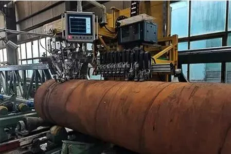
UT sends high-frequency sound waves into steel through a probe or transducer. A water- or gel-based couplant transfers sound. Reflected echoes return to the probe; their travel time and amplitude help inspectors locate discontinuities.
UT is useful for planar flaws such as cracks, lack of fusion, and incomplete penetration when the beam is correctly directed. Angle-beam probes examine weld regions and sidewalls. PAUT and TOFD provide additional imaging when specified.
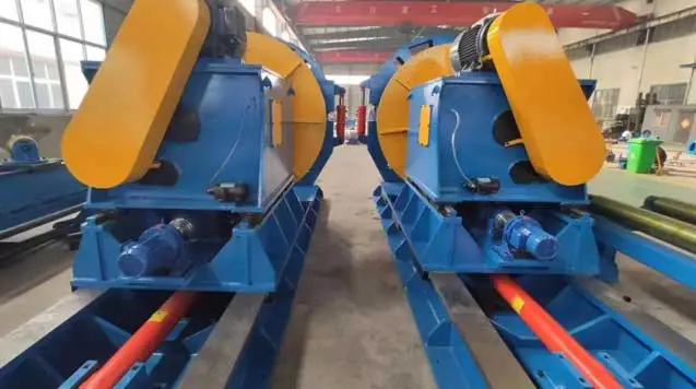
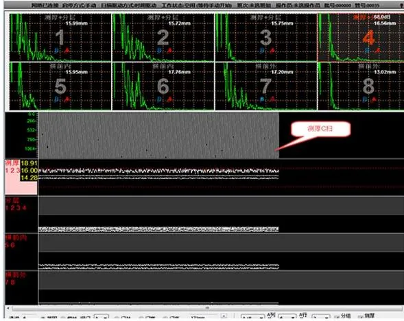
UT uses no ionizing radiation and supports rapid scanning. Results depend on surface condition, coupling, calibration, probe angle, geometry, and operator competence. Rough surfaces, near-surface dead zones, and unfavourable flaw orientation can affect detection. See ASNT's ultrasonic testing guide. Automated ultrasonic pipe testing equipment supports probe tracking, signal acquisition, and records.
Comparison | X-Ray Testing (RT) | Ultrasonic Testing (UT) |
Principle | Radiation passes through the weld and forms an image | Sound waves reflect from internal boundaries |
Typical strength | Porosity, slag, and other volumetric indications | Planar flaws, including cracks and lack of fusion |
Result | Film or digital image | Echo signals or scan data |
Main constraints | Radiation safety, access, and defect orientation | Coupling, surface condition, calibration, and beam direction |
How Do RT and UT Differ?
Neither is universally superior; results depend on flaw orientation, wall thickness, geometry, equipment, and procedure.
When Is Each Method Used for Spiral Welded Pipe?
RT is useful when an image record is needed or porosity and slag are key concerns. Setup must account for pipe dimensions, source and detector positions, and image quality.
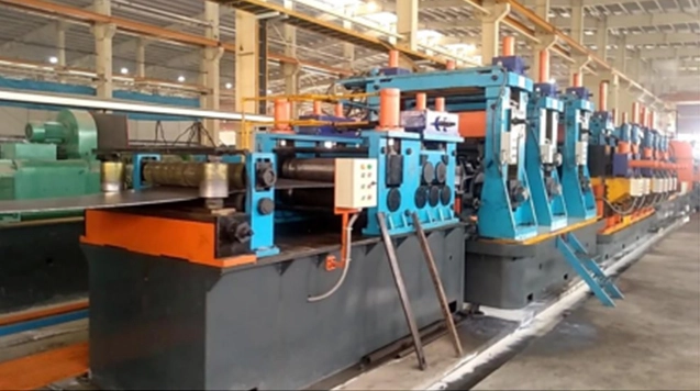
UT is useful when planar flaws or depth information matter, or when rapid scanning is preferred. Automated systems coordinate pipe movement, probe positioning, couplant, signal acquisition, and defect marking. When specifying a spiral welded pipe production line, buyers should define inspection method and coverage alongside pipe dimensions and output targets.
Can RT and UT Be Used Together?
Yes. RT provides images of many volumetric indications, while UT can be more responsive to planar flaws when the beam is correctly directed. Combined testing may reduce the blind spots of one method, but is not required for every pipe. Methods, coverage, and acceptance criteria must follow the applicable standard and project specification.
How Are RT and UT Integrated into a Spiral Pipe Mill?
Plan inspection according to material, diameter, wall thickness, weld geometry, coverage, and acceptance criteria. Before testing, clean the weld as required and confirm equipment condition and calibration.
For RT, position the source and detector according to the approved technique, control exposure, and retain the evaluated image. For UT, calibrate with a reference block, apply couplant, and scan the specified weld coverage. Record indications and re-examine repaired areas as required.
Chinese references include GB/T 11345-2023 and NB/T 47013.3-2023 for UT, and GB/T 3323.1-2019 and NB/T 47013.2-2015 for RT. Confirm applicable scope and editions for each project. Linking inspection records with the spiral pipe mill production stages supports pipe identification and traceability.
FAQs About RT and UT for Spiral Welded Pipe
1. Which method is better for detecting porosity?
RT generally provides a clearer image of volumetric indications such as porosity. UT may detect some pores depending on size, distribution, and setup.
2. Is UT better than RT for cracks and lack of fusion?
UT is often more sensitive to planar flaws when the beam is correctly directed. RT may miss tight flaws with unfavourable orientation.
3. Does RT require special safety controls?
Yes. X-ray and gamma-ray testing use ionizing radiation, requiring controlled areas, access restrictions, shielding, and qualified personnel.
4. Should every spiral welded pipe be tested by both RT and UT?
No. Method and coverage depend on product standards, service conditions, contracts, and project specifications. Combined testing is used when complementary examination is required.